‘Cerrem Mod’ – Kevin O’Connor’s Take On The Mod
Hi Guys!
I looked at the text above that described the mod Cerrem originally described. It is a pretty standard trick for controlling gain of differential stages.
A push-pull output stage is what you might describe as a “paraphase” stage instead of a differential stage. Paraphase stages typically receive two out-of-phase input drive signals, and producing two out-of-phase output signals. Differential amplifiers are very similar, but can be configured with single inputs or outputs. In the usual situation, the paraphase gain stages share a cathode resistor that behaves a bit like a current source, maintaining some semblance of balance in the output. These stages – like the paraphase driver in a Marshall Major – are resistively loaded.
You can reduce the gain of the paraphase stage (or any differential amplifier) by reducing the plate load. One way to do that is reduce the value of both plate resistors. Another way to do it is to strap a resistor across the plates, i.e., plate to plate. The load can also be a transformer which allows the paraphase outputs to be “added together”. The plate to plate load is what the total output stage sees, so if it is paralleled with another impedance, then the gain of the output stage is reduced.
To achieve significant signal reductions means going an order of magnitude lower than the starting impedance. A 4k or 5k OT might provide the optimum impedance to get 50W of output. Making this 400 to 500 ohms in total intuitively _increases_ prospective power output. However, we are not subbing in a lower-z OT, we are paralleling it with a plate to plate power resistor.
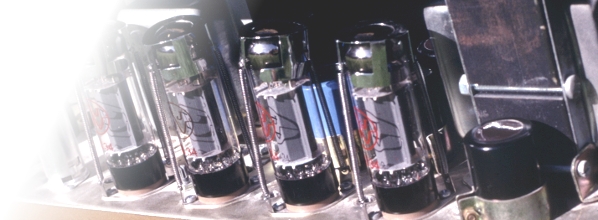
Indeed, the tubes will be working harder, with most of the power expended in the low impedance path instead of the parallel stock path. Intuitively, we might figure that about 90% of the power will be wasted in the resistor with 10% in the OT, which would give us a nice loudness reduction. What really happens is that the tubes DO try to deliver more power – not 10-times as much, but a significant amount more than they otherwise would try to deliver with just the OT – and that extra power is just wasted as heat. The reports from JP and others above verify that the tubes work very hard, to the point of running with red plates and sometimes burning out. Tubes are relatively inexpensive, so you might figure this is not a bad compromise. The danger lies in what else might be damaged when a tube fails: you could lose an OT, a PT, or both.
In lower power circuits, like a reverb driver, this method works very well. I use such an approach in my push-pull reverb driver to protect the transformer. However, the impedance ratio of the original circuit to the refined circuit was not as extreme as in the Cerrem example.
Although this is a very simple mod, there are risks involved. I would recommend you DO NOT DO IT IN ISOLATION. To reduce the risks, add some fast-blow fuses in series with each tube. This assures that no single-tube failure can take out the transformer.
The problem with fusing just the CT is that the fuse value must be high enough to accommodate the peak signal current for normal operation. In parallel output stages, this current might be quite high resulting in insufficient protection against reduced tube count failure modes.
Reduced audio output power is achieved, but the tubes may actually be working harder than if there was an attenuator between the amp and speaker. The sound is changed a bit, but not as much as an attenuator would do, and tube life is seriously reduced. Power Scaling would work a lot better without changing tone AND improve tube life AND give continuously variable loudness.
Sometimes, simple approaches work very well, but this one is fraught with potential hazards.
The dreamers among you might recognise above, another possibility – an expensive one: have the OT equivalent of a variac. Such a device would vary the effective plate load to the tubes thus vary the output power. The only realistic way to do this, comes from the welding world. Old variable output AC/DC power sources for stick welding had a variable reluctance core where a piece of core material is cranked into and out of the windings. This varies the resistance in the magnetic path, varying the output voltage and power that can pass through.
Have fun,
Kevin O’Connor
http://www.londonpower.com
Related posts:


